Flow Loop Testing to Determine Valve Performance Coefficients
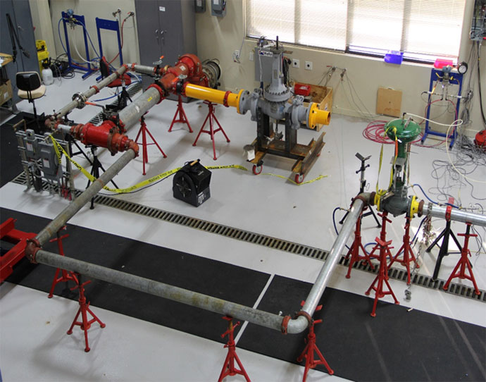
KEI™ flow loop facility is located in Sugar Land, TX. The main test section consists of a rapidly reconfigurable test section piping, a 7,500-gallon reservoir, a 180 HP diesel engine-driven variable speed centrifugal pump, and all associated piping for the actual test sections. The flow loop can deliver 2,700 gpm and pressures up to 270 psig. This flow rate corresponds to a flow velocity of 30 feet per second in a 6-inch pipe. Additional pump equipment can be connected to the system to achieve higher flow rates.
The main test section runs inside the air-condition laboratory, which allows for convent testing in all weather (see Figure 1). The KEI flow loop is frequently used to perform the following tests:
- Testing per ISA 75.02 to determine valve flow coefficient (Cv) and liquid pressure recovery factor (FL),
- Testing per IEC 60534-8-2 to measure flow-generated sound and vibration,
- Valve performance parameters such as hydrodynamic torque, flow-induced forces, and
- Fluid structure interactions.
KEI has on hand a wide variety of flow loop accessories and measurement equipment including
- A Y-pattern strainer with several sizes screen meshes. The finest screen mesh captures particles as small as 37 microns (click here to read more)
- A two-axis, pitot-static tube rake that can be used to measure the velocity profile across the pipe (click here to read more)
- A 3D pitot tube that can be used to measure velocity components across the pipe (click here to read more).
- Orifice meter bodies for a line sizes of 3-inch, 6-inch and 10-inch
- A high accuracy (0.15% of read), 4-axis ultrasonic flow meter for flow rates between 350 GPM and 4500 GPM.
- Accelerometers for measuring flow induced vibration (click here to read more)
- Sound measuring equipment and an anechoic chamber that excludes a wide frequency range of ambient lab noise to allow for precise flow-generated sound measurements (click here to read more)