Flow Loop Testing to Support Model Development for Balanced Globe Valves
The Kalsi Engineering Inc. (KEI)™ Flow Loop and Mechanical Testing facility was contracted to perform flow testing and Computational Fluid Dynamics (CFD) analyses to develop and validate methodology used to predict the required thrust to operate pressure-balanced globe valves. In addition to developing methodology, flow loop test data was used to validate the Computational Fluid Dynamics (CFD) predictions for the same valve types. The details of the CFD analyses is provided here.
Our mechanical and flow loop test engineers and technicians performed numerous flow-loop tests with the objective to:
- Validate CFD predictions over a wide range of flow/cavitation states, valve geometries, piping configurations, and fluid temperatures
- Identify critical parameters for the improved disk-to-cage friction force and disk differential pressure force methodology
- Validate the improved disk-to-cage friction force and disk differential pressure force methodology
- Develop coefficients that that can be used to predict disk DP force and disk-to-cage friction force requirements for a wide range of balanced globe valve models and disk styles
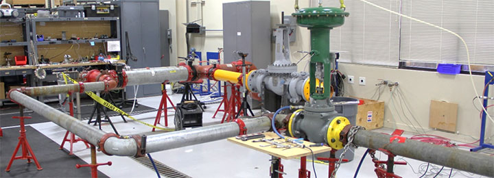
The KEI flow loop test set up is composed of the following
- A 7,500-gallon water reservoir
- Two variable speed centrifugal pumps operating in series
- An orifice plate flow meter with DP pressure transmitter
- Pressure transducers and DP transmitter to measure line pressure, bonnet pressure, and valve DP
- A position transducer to measure valve position
- A thermocouple to measure water temperature
- Modified actuator stems with load cells installed to measure actuator thrust
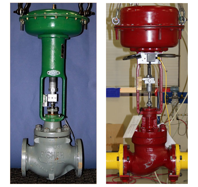
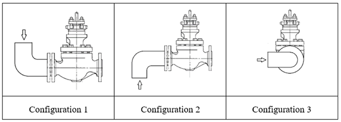
A total of 484 flow loop tests were performed. The test matrix consisted of tests for hot/cold fluid, static/dynamic strokes, different valve geometries, flow orientation (Flow Over and Flow Under), and three upstream pipe configurations. The data collected was used to calculate the valve flow coefficient (Cv), valve flow resistance (K), disk-to-cage friction force coefficient, and effective differential pressure area for combinations of flow characteristics of the globe valve trim set.
For more information on the CFD results on the balanced globe valve, click here. For additional information on KEI’s Flow Loop and Mechanical Testing capabilities, click here.