CFD Analysis of EPRI’s Globe Valve
Electric Power Research Institute (EPRI) contracted Kalsi Engineering Inc. (KEI)™ to develop a new methodology to calculate the thrust required to operate cage-guided balanced globe valves and cage-guided unbalanced globe valves. The project plan included these three key activities:
- Develop/refine a methodology to predict the flow-induced forces acting on the valve internals including analytical models for these predictions.
- Computational fluid dynamics (CFD) analyses were performed on a caged-guided, balanced globe valve under various operating conditions and plug positions.
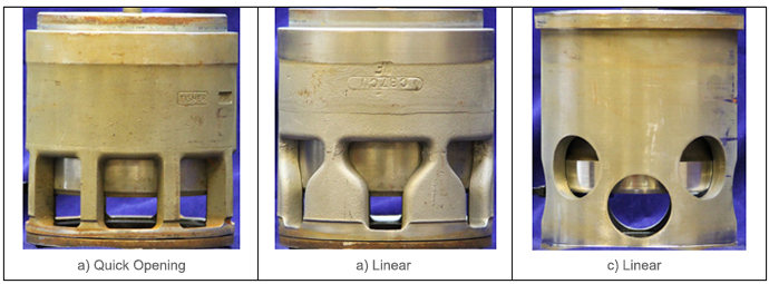
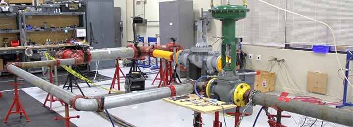
- Flow loop testing was performed on two caged-guided, balanced globe valves. The two specimens were of different make and one of the specimens was tested with multiple trim characteristics (see Figure 1). The flow loop test results for one specimen were used to confirm CFD predictions for that same specimen. The flow loop results for the second specimen were used to validate the valve required thrust methodology. Click here for more information about the flow loop testing.
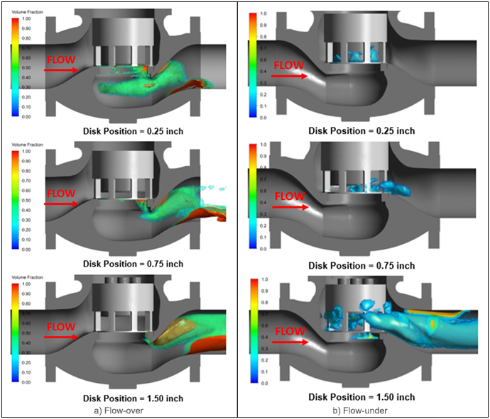
KEI used ANSYS CFX to perform the CFD modeling (see Figure 2). A key purpose of performing the matrix of CFD analyses was to develop valve performance coefficients that were needed to predict the differential pressure force (acting in the direction of the stem axis) and the side-load force (acting perpendicular to the stem axis and generally in the direction of the outlet.
The CFD matrix include different combinations of key parameters including flow state (single-phase incompressible flow, single-phase compressible flow, and two-phase flow), valve orientation (flow over or flow under), trim characteristics, cage design, and piping configurations. Over 150 CFD analyses were performed, and over 480 flow loop tests were performed for model validation. Two-phase flow predictions were used to understand how plug position and flow orientation affected the location of cavitation and how cavitation affected flow-induced forces.
The results of this project are currently incorporated in the Kalsi Valve and Actuator Program (KVAP), allowing the prediction of differential pressure and side-load forces for various balanced and unbalanced globe valve designs.