FEA of a Y-Pattern Globe Valve for Use in a Nuclear Generation Station
Motor-operated Y-pattern globe valves are used in the High-Pressure Coolant Injection (HPCI) and Reactor Core Isolation Cooling (RCIC) systems at a US nuclear power plant. The Y-pattern valve design utilizes three guide ribs to support the disc against high side-load forces. The guide ribs are evenly spaced circumferentially with two ribs flanking the bonnet-side outlet. The guide ribs flanking the outlet restrict the flow through the valve and greatly increase the side-load force, especially for the flow under orientation.
The subject valves are required to isolate against a High Energy Line Break (HELB). The flow-induced forces acting on the plug are significant due to the high line pressure and large flow rates present during an HELB. Previous flow loop testing on similar Y-pattern globe valves showed that the intensity of the disc-to-guide-rib reaction force (caused by the side-load force) is sufficient to cause galling and jamming of the disc in the guide ribs. To determine if the side-load forces were sufficiently high to cause damage for the 3-inch and 10-inch subject valves, KEI™ evaluated the stress and plastic deformation at the contact locations along the guide ribs using Finite Element Analysis (FEA). The contact stress and plastic deformation were evaluated at disc positions that were subject to the highest side-load forces. The side-load forces were determined via computation fluid dynamics (CFD) performed by KEI.
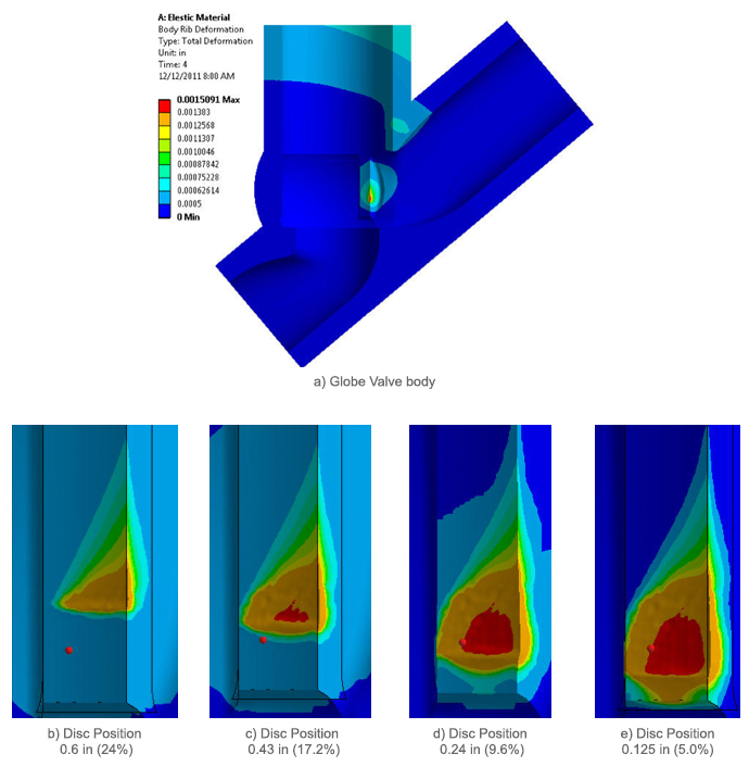
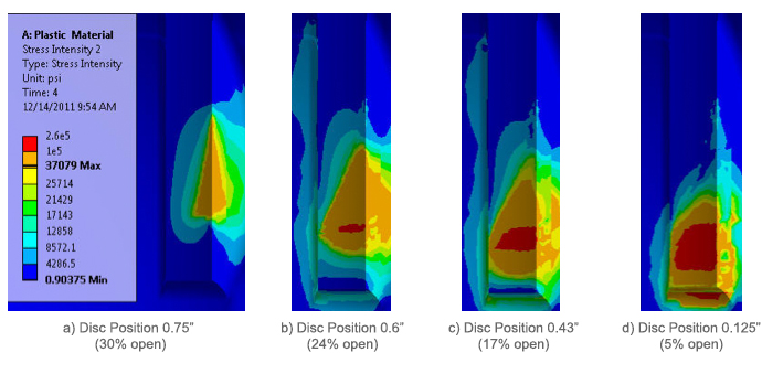
The results for the total deformation along the guide rib for the 6-inch valve (which has a different disc design than the installed valves) from the elastic-plastic analysis are provided as Figures 1 and 2. The severity of the disc-to-guide-rib reaction load for the 6-inch valve caused the material on the guide to “mound” at the leading edge of the disc. The mounding of material greatly increased the traction forces required to move the disc along the guide, which resulted in a larger than expected valve required thrust.
Based on the FEA results of the actual 3-inch and 10-inch valve, it was determined that the side-load force was not sufficiently high enough to plasticly deform the guide-rib and therefore normal slide friction loads are expected. As such, the mounding process is not present and will not impede valve closure.
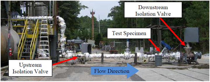
KEI also conducted Flow Testing under steam blowdown conditions to validate the predictions. Comparison of the testing results with the FEA and CFD predictions of the analytical model showed agreement. For more information about the CFD analyses conducted on the globe valve click here.