CFD Analysis of a Y-Pattern Globe Valve
Motor-operated Y-pattern globe valves are used in the High-Pressure Coolant Injection (HPCI) and Reactor Core Isolation Cooling (RCIC) system at a US nuclear power system. The Y-pattern valve design utilizes three guide ribs to support the disc against high-side load force. The guide ribs are evenly spaced circumferentially with two ribs flanking the bonnet-side outlet. The guide ribs flanking the outlet restrict the flow through the valve and greatly increase the side load force – especially for the flow-under orientation. The subject Y-pattern globe valves are mounted in pairs (installed in series). The subject valves in the HPCI system are 10-inch, and the subject valves in the RCIC system are 3-inch. The inboard valve is installed in the flow-over orientation and the outboard valve is installed in the flow under orientation. The subject valves are required to isolate against a High Energy Line Break (HELB). Due to the high line pressure and large flow rates present during an HELB, the flow-induced forces acting on the plug are significant.
Kalsi Engineering was contracted to determine the operating requirements and the survivability of the Y-pattern globe valves during their isolation function against HELB conditions. Kalsi Engineering developed a proprietary analytical model to account for system pressure conditions, flow-induced forces, and sliding friction (caused by flow-induced side-load forces). Kalsi Engineering performed extensive CFD analyses to develop valve performance coefficients, including flow coefficients, flow-induced force coefficients, and compressibility factors. Kalsi Engineering also evaluated the potential for side-load induced damage (e.g., galling and scoring) using Finite Element Analyses (FEA).
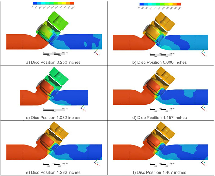
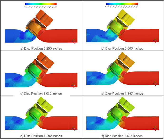
ANSYS CFX (computational fluid dynamics (CFD) software) was used to determine the flow-induced forces for three different valve sizes under both compressible and incompressible flow at key disc positions. The valve sizes included in the CFD study were 3-inch valve, 6-inch, and 10-inch. The 6-inch valve was included in the CFD matrix as it was the valve used in previous industry testing. The pressure field acting on the valve is provided for several disc positions in Figures 1 and 2 for the flow under and flow over orientation, respectively.