Globe Valve Internals Damaged due to High Side-Load Forces
Globe valves are used to isolate steam lines in power plants in the event of a pipe break; such pipe breaks are referred to as High Energy Line Breaks (HELB).
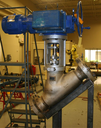
KEI™ performed a Failure Modes and Effects Analysis (FMEA) for a Y-pattern globe valve that operated in the High-Pressure Coolant Injection System. The purpose of the FMEA was to determine the possible failure modes that might prevent the valve from closing and isolating under HELB conditions. The Y-pattern globe valve (Figure 1) included three internal body-ribs that guided the plug. The valve differential pressure condition and associated high plug-to-guide-rib loading, was identified as a possible failure mechanism that could lead to rib galling or wear.
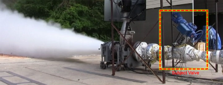
The subject valve was tested under HELB conditions (see Figure 2) to determine if plug-to-rib galling or rib damage occurred and whether the damage would result in an increase in required thrust that would prevent the operator from actuating the valve to the fully closed position.
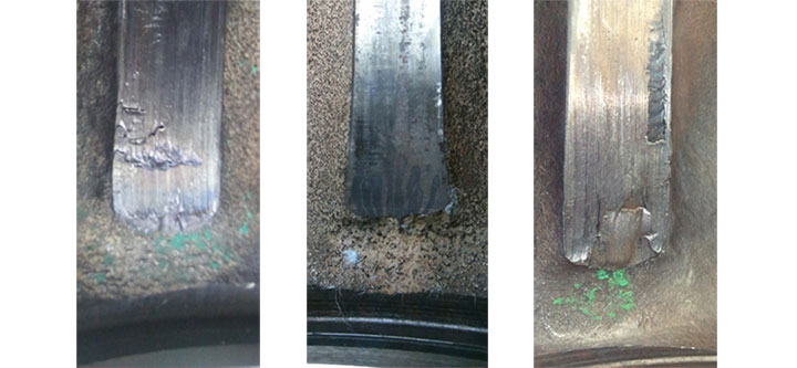
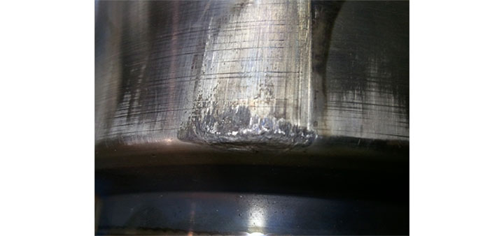
The testing confirmed the subject valve was susceptible to plug-to-rib damage for certain plug geometries in certain flow orientations. The flow-under orientation was determined to be the most severe for this particular valve. Figure 3 shows guide-rib damage (on the 120° and -120° rib) caused by high side load forces that occur under HELB conditions. Figure 4 shows corresponding damage on the leading edge of the plug.
To support the FMEA and root-cause analysis, KEI developed an analytical model based on plug geometry and operating conditions was developed to predict the thrust required to operate the valve and plug-to-rib loading in the presence of flow-induced side-load forces. The analytical model utilized fluid-force coefficients based on Computational Fluid Dynamics (CFD) analysis. The CFD-based fluid force model was used to perform Finite Element Analysis (FEA) of the plug-to-guide rib reaction. The flow test data validated the CFD analysis and verified that FEA could be used to predict guide rib damage for other plug geometries and system conditions.