Failures due to Thermal Distortion/Stresses
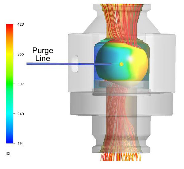
KEI™ performed a detailed analysis of a metal-seated ball valve to assess the potential failure mode due to thermals stress cracking. The subject valve carried high-temperature liquid hydrocarbons. The subject valve utilized a purge line and cooler purging fluid to displace/remove the hydrocarbons from the body/seat cavities.
CFD analysis was performed to calculate the temperature throughout the valve body due to mixing of the two fluids (see Figure 1). The temperature profile from CFD analysis was used to perform thermo-structural FEA (see Figure 2). The stresses from the FEA were used to calculate the fatigue life of the valve.
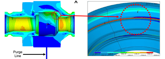
a) Stress distribution along the body cross-section
b) Local stress distribution along body cavity
Figure 2: Thermal-Structural FEA Results Showing High Thermal-Induced Stress in the Body Cavity Grooves.