Rigorous Approach to Address Flutter-induced Damage of Large Butterfly Valves
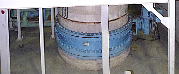
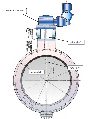
A power plant experienced reoccurring failure of torque train components in large butterfly valves due to disc oscillations (i.e., disk flutter). The large butterfly valves were installed in condenser inlet lines of the circulating water system. Frequently damaged components include disc pins, shaft, or quarter-turn gear box components. Kalsi Engineering, Inc. (KEI) was tasked with resolving the disc flutter and chronic failures in the motor-operated butterfly valves.
When large butterfly valves are positioned at a disc opening angle of approximately 70° to 90°, the valve disc can experience hydrodynamic torque fluctuations that approach or exceed the magnitude of the time-averaged value. The hydrodynamic torque fluctuations generate varying stresses in the torque train components that can cause fatigue failure.
Hydrodynamic torque reversals can cause the disc to flutter. Disc flutter can result in impact loading in the torque train components. Because high inertial forces can exist during impact loading, impact loading can greatly increase the magnitude of the alternating stress in the torque train components (e.g., disc pins, shaft, or quarter-turn gear box components) and accelerate fatigue related damage.
For several years, the plant attempted to solve the problem by replacing the failed components with stronger ones. However, this simply changed the failure point to the next weakest link in the torque train.
KEI laid out and followed a systematic approach of quantifying the disc fluctuations and levels of alternating stress and subsequent fatigue life so that a complete fix could be recommended to the plant. This systematic approach included the following key tasks:
- Consider potential effects on power generation due to changes in the valve or valve position
- Utilize KEI’s vast library of flow loop test results for quarter turn valves to quantify effects due to flow disturbances, disc position, and disc type.
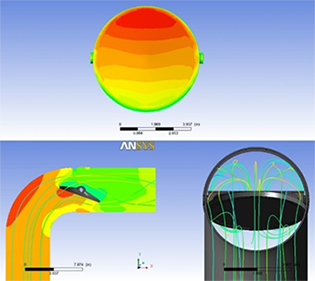
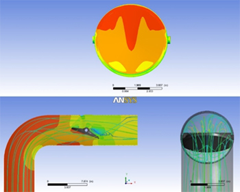
- Perform Computational Fluid Dynamics (CFD) analysis to better quantify the fluctuations in hydrodynamic torque, including upstream elbows as shown in Figures 2a and 2b.
- Perform structural strength and fatigue analysis to ensure recommendations will prevent subsequent failure.
KEI staff are very familiar with flow-induced phenomena in butterfly valves as a result of performing a large number of incompressible and compressible flow loop tests on butterfly valves. Additionally, KEI has gained additional insight through rigorous use of CFD to this specific application. KEI calculated the magnitude of the mean and fluctuating hydrodynamic torque values so that the stress in the torque train could be quantified.
After all factors were investigated, Kalsi Engineering presented the solution to the plant. KEI recommended the optimum conditions which have prevented fatigue failure. Our consulting engineers were able to formulate a long-term detailed solution based on their in-depth root-cause investigations.
For valve engineering services, contact us here.