Flow Testing

Our flow loop was especially designed to investigate flow-related problems with valves used in typical power and process plant applications. The facility has been used to perform thousands of tests on nuclear and commercial check valves, butterfly valves, gate valves and plug valves for various clients including power generation utilities, valve manufacturers, and EPRI.
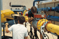
The flow testing facility comprises three major sections: 1) the control and instrumentation building; 2) an all-weather outdoor bay housing the hydraulics section; and 3) the adjacent main laboratory. The main hydraulics section consists of a rapidly reconfigurable test section piping, a 7,500-gallon reservoir, a 180 HP diesel engine-driven variable speed centrifugal pump, and all associated piping for the actual test sections. The flow loop is capable of delivering 2,700 gpm and 270 psig. This flow rate corresponds to a flow velocity of 30 feet per second in a 6-inch pipe.
The test section is of modular construction, allowing rapid piping configuration changes. Victaulic® couplings eliminate the need for expensive custom pipe welding and time-consuming bolted flanges. The laboratory has a large inventory of pipe spools, fittings, and flow control valves to support testing activities. The flow metering section utilizes orifice plates and a high-accuracy differential pressure transducer to provide flow rate data. The meter run is constructed in accordance with the requirements of ANSI/API Standard 2530, providing a flow accuracy of ± 0.5 percent.
Electronic equipment, pump controls, and valve controls are housed in the instrumentation building next to the flow loop hydraulics area. Test instrumentation feeds data directly to a high speed computerized digital data acquisition system which can display and process the data in real time. A variety of pressure, temperature, displacement, load, and other transducers is available.
