Thermal-Hydraulic Modeling of a Postulated Main Steam Line Break using RELAP
Kalsi Engineering Inc. (KEI)™ evaluated the operational readiness and survivability of the Main Steam Isolation Valves (MSIVs) installed in the main steam line (fed by the steam generator) of a nuclear power plant as part of a planned Extended Power Uprate (EPU) project. It is necessary to ensure valve operation and survivability are not compromised by the increase in flow-induced forces caused by the increase in mass flow rate associated with the EPU.
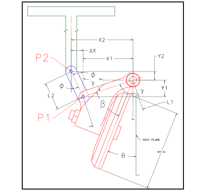
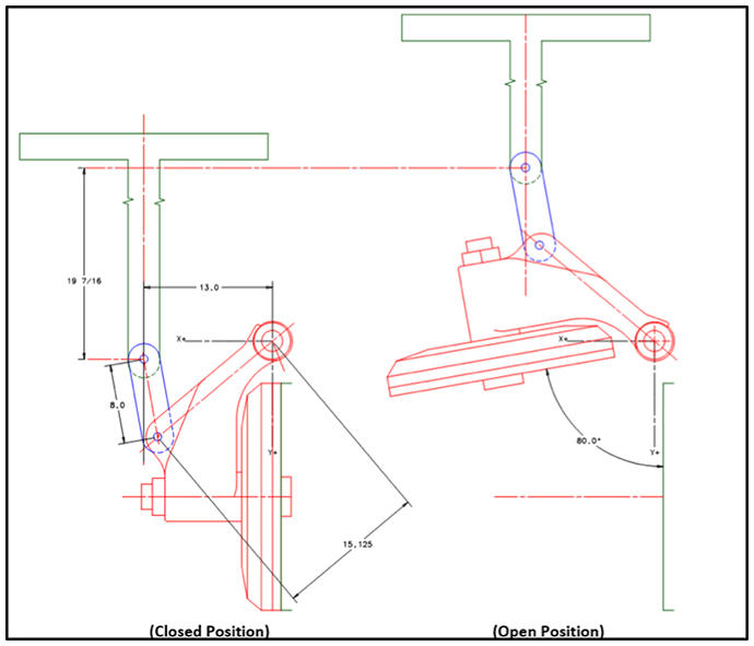
Key tasks completed as part of this project included determining the maximum disk impact velocity for spurious closure and pipe break for the new EPU conditions. To complete these tasks, KEI developed a kinematic model of the MSIV actuator and valve components and a dynamic model of the pneumatic actuator output force and flow-induced forces on the valve. The actuator output force model required transient pressure predictions based on the venting process of the actuator. Key components and dimensions for the kinematic model are shown as Figure 1. The position of the disc, linkages, and actuator stem and piston for the full open and full closed positions are illustrated in Figure 2.
The dynamic models were incorporated into the Reactor Excursion and Leak Analysis Program (RELAP). The integrated model was used to predict disc impact velocity under spurious closure conditions under high energy line pipe break conditions.
The sequence of modeled events for the spurious closure was as follows:
- Signal to close is issued and the venting process for the pressure in the actuator begins.
- As the actuator pressure decreased, the closing force generated by the actuator spring, weight of the moving parts, and self-closing flow-induced forces begin moving the disc closed.
- As the disc closes, the thermal hydraulics model (RELAP) calculates the differential pressure acting across the MSIV based on the system response associated with the change in disc position.
- As the disc closes and net transmitted torque/force is calculated based on the updated values for the actuator output force and flow-induced force.
- The net torque/force is integrated in the time step, and the angular acceleration, disc velocity and disk position are updated.
- As the disc closing speed increases, the actuator pressure cannot vent quickly enough and the gas in the actuator is compressed causing a significant increase in the pressure force opposing motion. Due to the rapid compression, actuator pressure achieves a value such that the actuator force acts in the opening direction and tries to slow the disc. Significant loads can be experienced by the linkage when the actuator resists closure.
The sequence of modeled events for the pipe break is the same as for spurious closure with the exception that the load transmitted to the linkage pin is monitored, and when the load at the pin reaches a defined limit, the model considers the actuator to separate from the disc. Disc separation allows the flow-induced forces to accelerate the disc to a higher impact velocity.