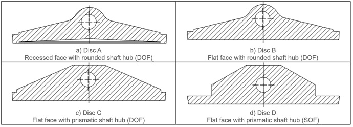
Study of the Effects of Disc Geometry
Kalsi Engineering Inc. is the leading expert in valve technology. An area of specialized expertise is in predicting the torque required to operate butterfly valves. A key component of the required torque is the hydrodynamic/aerodynamic torque. Kalsi Engineering has actively developed improved semi-empirical analytical models for predicting hydrodynamic torque for over 25 years. Kalsi Engineering has performed numerous water flow and compressible flow tests to determine by experiment the hydrodynamic torque for a many common disc shapes. Key factors that influence the hydrodynamic/aerodynamic torque on a valve such as:
- Valve installation orientation (shaft upstream vs. downstream)
- Disc geometry
- Velocity skew due to flow disturbances
- Fluid media
Kalsi Engineering completed a matrix of Computational Fluid Dynamics (CFD) analyses to better understand the effect subtle changes in disc geometry had on hydrodynamic/aerodynamic torque. ANSYS CFX was used to complete the CFD matrix. The matrix included four different disc geometries (see Figure 1). Each disc was analyzed in the shaft upstream and downstream orientations for both compressible and incompressible flow conditions.
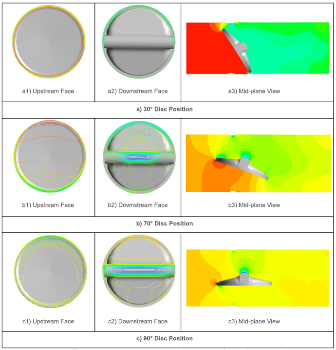
The change in differential pressure profile acting on the disc for key disc positions is provided in Figure 2.
The CFD results were used to develop valve performance parameters such as flow coefficients, hydrodynamic torque coefficients, flow-induced bearing force coefficients, and compressibility factors. These coefficients are used to predict required torque for a wide range of valve sizes and styles in a wide range of operating conditions. The CFD results provided insight into the dependency of the performance coefficients on the disc geometries.
The understanding gained from this study was incorporated in the Kalsi Valve and Actuator Program (KVAP®), allowing the prediction of valve dynamic torque for various flow conditions.