Analytical Model Development
Kalsi Engineering’s capability to develop and validate analytical models has been proven by multiple projects for several types of valves. One example of particular interest is Kalsi Engineering’s work related to the development of an analytical model to predict required stem thrust to operate a Y-pattern globe valve. This project required three key components to ensure an accurate and conservative model was developed. The three components included (1) developing an analytical model, (2) performing CFD to determine modeling coefficients, and (3) performing testing to validate the model.
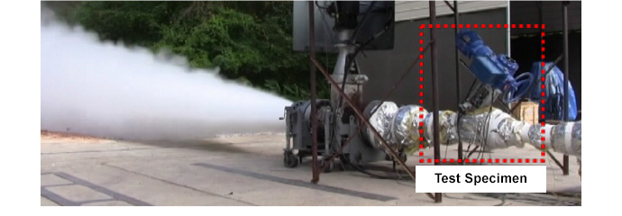
Y-pattern globe valves are used at some nuclear power plants to perform an isolation function during loss of coolant accident conditions. During a loss of cooling accident, the valve is required to close and isolate a high-energy line break. During a high-energy line break scenario, the valve is subjected to considerable side-load forces due to the high velocity flow. Y-pattern globe valves have guide ribs that support the plug during actuation.
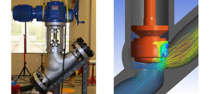
Stem thrust predictions for Y-pattern globe valves require calculating the friction force associated with the plug being driven down the guide rib by the actuator while the plug is subjected to a flow-induced side-load force; as such, developing an accurate model required understanding the flow-induced side-load force acting on the plug and the resulting reaction force between the plug and guide ribs. Kalsi Engineering performed CFD modeling of the Y-pattern globe valve to ensure the side-load force could be accurately predicted by the analytical model (see Figure 1).
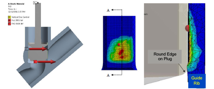
In addition to the CFD predictions, Kalsi Engineering also performed elastic-plastic FEAs to determine the potential for guide rib damage due to valve closure under high side-load forces. The FEA predictions for plastic deformation of the guide rib, provided as Figure 2, showed that damage was possible when the side-load force was sufficiently high.
The analytical model was validated against the measured stem force obtained during actual steam blow down testing (see Figure 3). The test conditions consisted of 1000 psi steam pressure discharging through the subject valve to atmospheric conditions. The guide ribs experienced damage during testing similar to that predicted by FEA.