MOV Actuator Test Stand
Our Clients
The Kalsi Engineering MOV Actuator Test Stand provides electric power stations with an efficient way to verify and calibrate torque output of MOV actuators, and to determine their performance characteristics. It is used to accurately evaluate actuator performance off-line and eliminate potentially expensive damage to the MOV by enabling the following parameters to be monitored:
- Torque switch settings for gate, globe, and butterfly actuators
- Changes in torque output under applied stem thrust (gate and globes)
- Stall capability
- Gear efficiency (with optional motor torque measurement device)
The test stand is also used to identify and diagnose refurbishment problems associated with:
- Thrust bearing damage
- Torque switch imbalance
- Improper assembly, which can cause loss of output; e.g., worm-to-worm gear misalignment, thin gaskets, excessive pre-load on housing cover bolts.
The units span a torque range of 12.5 to 3,600 ft-lb, with accuracy and repeatable performance across the entire range. This wide range of sensitivity is accomplished by selective employment of pneumatic disk brakes, and by utilizing different load cells to cover the entire torque range. Adapter plates and stem adapters are available for actuators made by Limitorque, Rotork, EIM, Hopkinsons, and others.
View Our Motor-Operated Valve Technology and Services
Contact Kalsi Engineering to learn how the MOV Actuator Test Stand can aid your engineering and maintenance staff assess actuator health.
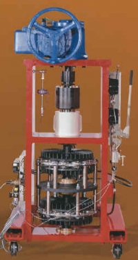
How It Works
The actuator mounts on top of the test stand with an adapter plate, and is coupled to the stand by a stem adapter which replaces the actuator stem nut. The stem adapters are not threaded, and there is no vertical travel of the stem in the actuator. Thrust and torque are applied independently and can be adjusted to any level.
The loading system applies a constant thrust load via a double-acting hydraulic cylinder. The cylinder provides upward or downward loads to simulate opening or closing valve strokes. The hydraulic load is transmitted to a shaft shoulder through self-aligning roller thrust bearings, and is applied to the actuator by the stem adapter.
Actuator torque is transmitted from the stem adapter to the test stand drive shaft by a slotted drive connection. A controlled torque reaction is applied to the actuator by varying the pressure to the drive shaft pneumatic brakes. The torque can be varied from zero to the test value within a prescribed time by setting the target torque and time.
Stem thrust, stem torque, motor torque, and motor speed are measured using sensors and instruments which are easily removable, and are calibrated to nationally recognized standards.
Test Stand Features and Capabilities
Torque Resistance
- Resistance Is Provided By Industrial Pneumatic Disc Brakes
- Variable Ramp Time
- Variable Target Torque
Data Input and Control
- Computer Controlled Electronic Interface
- Digital Set-Point Data Entry
Data Display
- Operator RPM
- Thrust Load
- Operator Output Torque
- Spring Pack Displacement
Analog Output
- BNC Connectors for Chart Recorder, Computer or Motor Power Monitor
Options
- Power Cabinet with Variable Motor Voltage Selection
- Power Cabinet with Discrete Motor Voltage Selection (145, 166, 208, 400, 460, and 575 VAC)
- Motor Torque Measurement Device for Limitorque Actuators (2-80 Ft-Lb capacity)
Operator Adapters
- Limitorque SMB-000 to SMB-2
- Limitorque H0BC to H2BC
- Rotork Sizes 7 to 90
- EIM and Hopkinsons
Load Range
- Zero To 75,000 Pound Thrust Range, Tension or Compression
- 12.5-3,600 Ft-Lb Torque Range, Bi-Directional