Check Valve Wear and Failure Analysis
Check valve issues became a focal point in the US nuclear power industry during the 80s and 90s. Multiple check valve failures prompted the US NRC to issue several notices related to check valve maintenance and in-service testing.
The consequences of check valve failures can range from expensive unplanned down time to causing severe accidents that may results in the loss of life.
Check valve failures often result from the wear or damage of key components such as the hinge pin or back stop. Wear of these components often is the result of an oversized valve installed near an upstream flow disturbance, which results in insufficient flow velocity to pin the disk fully open. As a result, the disk oscillates and/or taps. Disk oscillation can produce significant wear in a relatively short amount of time.
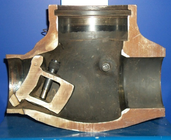
Wear of these components can impede proper valve operation including failure to close and check against reverse flow, and in extreme cases can cause complete separation of the disc, as was experience by one US power plant. Due to excessive wear the disc completely separated from the support point and became lodged in the valve outlet, which prevented flow in the normal direction (Figure 1).
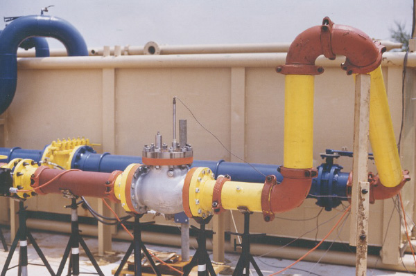
Kalsi Engineering undertook an extensive test program and studied the wear rates under various flow conditions (Figure 2). Kalsi Engineering also led an industry effort to develop maintenance guidelines and predictive routines for multiple check valve models. The wear rates based on flow conditions were extended to other material types and were ultimately used to develop the CVAP® software, which has become the industry standard for assessing check valve degradation. Results from CVAP are used to (1) identify flow conditions that could lead to accelerated wear and (2) to develop maintenance intervals to ensure check valve failures do not occur during plant operation. CVAP can also be used to assess design improvements.