The Pressure Capacity of PTFE Lip Seals vs. KLS Seals
Advantages of KLS® spring-loaded lip seals
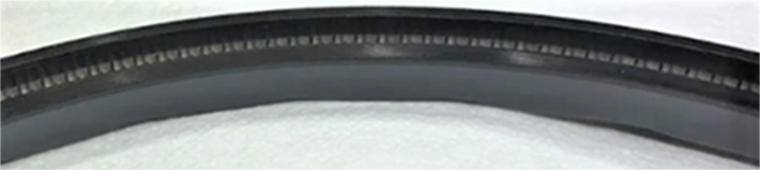
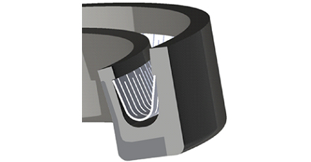
KLS seals are a type of spring-loaded lip seal that was developed to overcome the pressure limitations of PTFE lip seals. They accomplish this by incorporating patented hydrodynamic waves that pump a thin film of lubricant from the low-pressure side of the seal to the high-pressure side during rotation. This pumping action causes the seal to hydroplane on the film of lubricant, which dramatically reduces friction, wear, and seal-generated heat. As a result, KLS seals can achieve significantly higher speeds than conventional non-hydrodynamic PTFE lip seals when operating in the 500 to 1,500 psi (3.45 to 10.34 MPa) pressure range.
By relying on hydrodynamic interfacial lubrication to minimize friction, wear, and seal-generated heat, the plastic portion of KLS lip seals can be selected for pressure resistance rather than low friction characteristics, and does not need abrasive filler materials to address creep and wear.
Pressure and speed capacity of the KLS lip seal design
The following table shows the test pressures and speeds the KLS has survived in laboratory duration testing directed at the challenging oilfield Rotary Control Device (RCD) seal market. The seals have also been tested at 543.40 sfpm (2.76 m/s) at pressure increments ranging from 100 to 1,000 psi (0.69 to 6.89 MPa). As a result of their remarkable performance, KLS lip seals have become our most popular large diameter rotary shaft seals.
| Shaft diameter | Pressure | Shaft Speed | ISO VG oil | Duration, hours | ||||
|---|---|---|---|---|---|---|---|---|
| Inch | mm | psi | MPa | rpm | sfpm | m/s | ||
| 3.375 | 85.73 | 1,000 | 6.89 | 615 | 543.40 | 2.76 | 150.00 | 200+ |
| 10.500 | 266.70 | 1,500 | 10.34 | 50 | 137.44 | 0.70 | 320.00 | 200+ |
| 3.375 | 85.73 | 1,500 | 10.34 | 155 | 136.95 | 0.70 | 460.00 | 200+ |
For control purposes, we manufactured a lip seal like the KLS but with a carbon-graphite filled PTFE liner and no hydrodynamic waves. They failed in a few hours of operation at 500 psi (3.45) and 543.40 sfpm (2.76 m/s).
For information on implementing KLS seals, see Chapter C17 of our sealing handbook. The waves of a KLS lip seal are for one direction of shaft rotation only. If bidirectional rotation or higher pressure and speed combinations are required, consider our BDRP seal.
About Kalsi Engineering, Inc.
Kalsi Engineering, Inc. was founded by M. S. Kalsi, Ph.D. in 1978 and began as a consulting engineering company. Dr. Kalsi’s Ph.D. research led to a rotary shaft seal product line that is based on hydrodynamic interfacial lubrication. Continuing R&D has led to seal designs with significant pressure capability, such as KLS lip seals. Contact us for additional information and implementation assistance.

Limitations of spring-loaded PTFE lip seals
Spring-loaded PTFE lip seals are widely used for rotary sealing applications, and for good reasons. In low differential pressure conditions, PTFE lip seals run well and can tolerate surprisingly high speed due to the relatively light lip load and the low friction characteristics of the PTFE-based seal material. In our testing, however, the running torque of PTFE lip seals increased dramatically at 500 and 1,000 psi (3.45 and 6.89 MPa) — even at the very slow rotary speed of 28.80 sfpm (0.15 m/s) — and was more than double the torque that was generated at 50 and 100 psi (0.34 and 0.69 MPa).
Seal-generated heat increases with torque and with speed but is not proportional to speed. Instead, seal-generated heat increases faster than the increase in speed. As a result, PTFE lip seals operating with high differential pressure are prone to overheating at what may seem like reasonable surface speeds.
PTFE is remarkable for its low friction characteristics, but its creep behavior under load makes it unsuitable as a seal material in its virgin unfilled state. Various fillers are added to PTFE lip seal materials to reduce creep and wear and increase strength. Beware that some of the fillers recommended for rotary service are abrasive and can wear the mating surface of the shaft.
The KLS seal design overcomes the pressure limitations of PTFE lip seals by addressing friction with hydrodynamic lubrication, which allows seal materials to be selected for pressure resistance instead of frictional properties.