KEI is committed to providing superb engineering services to our valued customers. In early 2021 KEI will complete an upgrade to our flow loop that will allow us to expand our services. The upgrade will reduce the back pressure on the test section and allow for extended Flow Coefficient (Cv) and Liquid Pressure Recovery Factor (FL) testing.
Original Flow Loop
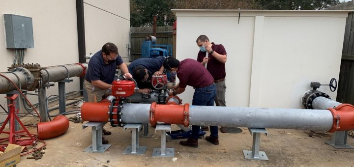
The original KEI flow loop was located in the KEI parking lot (see Figure 1). Despite its humble appearance, KEI used the flow loop to perform extremely valuable testing during its 18+ years of service. Several of our early flow loop testing programs were critical to the US nuclear power industry.
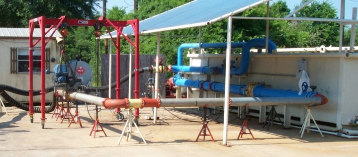
Figure 1
Original KEI Flow Loop Located in the Parking Lot
KEI originally designed and assembled the flow loop in the late 80s to support check valve wear and fatigue research performed as part of a Small Business Innovation Research (SBIR) award for the Department of Energy (DOE). KEI’s work in developing and validating check valve wear and fatigue models was used to develop KEI’s Check Valve Analysis Program software CVAP. KEI also used the check valve testing to develop industry guidance for EPRI documents. The nuclear power industry still uses CVAP to verify that check valve function is not compromised by unexpected in-service wear and fatigue.
KEI used the original flow loop in the early 1990s to conduct quarter-turn valve testing as part of an EPRI funded program. KEI used the quarter-turn test data to develop and validate semi-empirical models. These models are used to predict the torque required to operate quarter-turn butterfly valves. In the late 90s and early 2000s, KEI self-funded additional quarter-turn valve testing and developed a more comprehensive library of quarter-turn test data. KEI incorporated the comprehensive data into KEI’s Valve and Actuator Prediction software KVAP, which is used extensively in the US and international nuclear power industry to determine operating margins for safety-related air-operated and motor-operated valves. KEI continues to perform flow loop testing on client specific valves and pipe installations to establish basis for operating under design basis accident conditions.
2008 Flow Loop Refurbishment
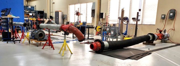
As part of our building expansion in 2008, KEI refurbished and relocated the flow loop. The hydraulic pumping system was relocated behind the main consulting lab, and the test section runs inside our main consulting lab (Figure 2). The KEI flow loop continues to be an integral part of the KEI consulting business and has been used to support industry test projects and KEI-funded initiatives. Industry projects include flow loop testing for the Nuclear Industry Check Valve (NIC) group, EPRI flow loop testing to measure required thrust for globe valves under high flow conditions, and flow loop testing to develop flow conditioners.
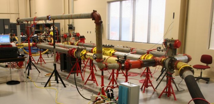
2008 Flow Loop Relocation with Test Section Located Inside Main Consulting Lab
2021 Flow Loop Upgrade
KEI is currently upgrading the flow loop return line to further expand our flow loop test capabilities. The existing return line is a 6-inch line. The new return line is a 10-inch line. Upgrading the return line from 6-inch to 10-inch will reduce the differential pressure across the return line by about 87%. Figure 3 and Figure 4 provide the achievable vena contracta pressure (pressure inside test specimen) for various FL values for the 6-inch and 10-inch lines. Figure 3 shows that the vena contracta pressure in a test specimen is prohibitively high to conduct FL testing for FL values above 0.4 due to back pressure provided by the 6-inch return line. Figure 4 shows that the back pressure is reduced significantly, and that it is possible to generate a vena contracta pressure (in a test specimen) below the vapor pressure (Pvap), which is required for FL testing.
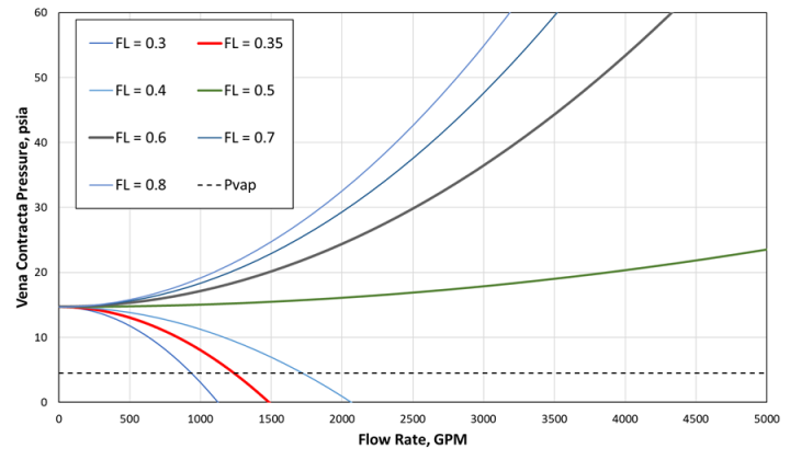
Vena Contracta Pressure for Key FL Values for the KEI Flow Loop with 6-inch Return Line and Water Temperature of 160 °F
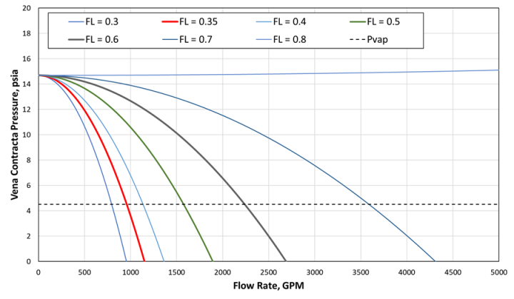
Vena Contracta Pressure for Key FL Values for the KEI Flow Loop with 10-inch Return Line and Water Temperature of 160 °F
Figure 5 and Figure 6 show the current progress on the return line at the tank connection and at the wall penetration.
Installation of 10-inch Return Line to the KEI Flow Loop Tank.
Installation of 10-inch Return Line at the Wall Penetration of the KEI Flow Loop
Contact the Kalsi Engineering Consulting staff to learn how we can assist you with your flow loop testing needs.