Introduction to high pressure seal implementation challenges
Mechanical designers face five significant challenges when implementing high pressure rotary seals: shaft runout; shaft misalignment; shaft deflection; pressure-related hardware deformation; and the dissipation of seal-generated heat. These challenges, and their solutions, are described below. The video included above shows how our patented floating backup ring addresses the first four challenges.
The scope of the video is explaining how the floating backup ring assembly works as a high-pressure oil seal. For information on how to use floating backup rings in combination with barrier seals to retain fluids other than oil, see Chapter D17 of our handbook.
Understanding why high-pressure extrusion damage occurs
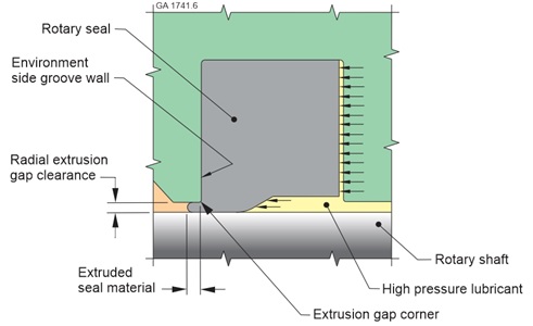
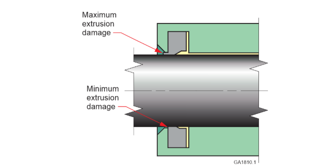
Polymeric rotary seals are typically installed in a housing groove and compressed radially between the groove and a bearing-guided rotating shaft to establish sealing (Figure 1). The purpose of the seal is to prevent fluid loss through the necessary clearance that exists between the seal housing and the shaft. This clearance is commonly referred to as the “extrusion gap” because high pressure causes seal material to extrude into the clearance and break away from the seal in a process that is known as “extrusion damage”. In high pressure service, the extrusion damage process may continue until the seal is destroyed.
Extrusion damage occurs as a result of stress in the extruded seal material. For example, shaft runout causes the extruded material to experience repetitive compression and relaxation cycles. Runout also causes cyclic seal material movement relative to the “extrusion gap corner” that is present between the bore and the groove wall of the housing. The resulting stresses cause the extruded material to break away from the seal. As more material is extruded into the gap, the seal is eventually consumed and can no longer maintain a seal with the shaft.
The smaller the extrusion gap, the less the extrusion damage. As discussed in more detail below, there are limits to how small an extrusion gap can be made with a conventional seal housing and bearing-guided shaft. The floating backup ring overcomes these limitations and allows the use of an extremely small extrusion gap that minimizes high pressure extrusion damage.

The challenges of shaft runout, misalignment, and deflection
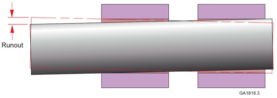
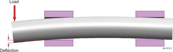
Shaft runout, misalignment, and deflection are phenomena that are somewhat overlapping in nature. Shafts experience dynamic runout for a variety of reasons, such as bearing internal and mounting clearances (Figure 3), eccentrically machined shaft surfaces, and equipment vibration. Side loads create shaft misalignment relative to the housing due to factors such as bearing internal and mounting clearances. Shaft misalignment can also occur due to other factors, such as mounting clearance between a seal housing and a bearing housing. Side loads also cause elastic lateral shaft deflection (Figure 4). If the magnitude or location of the load changes, the resulting changes in deflection contribute to the magnitude of dynamic runout. Static misalignment increases extrusion gap clearance on one side of the housing (Figure 5), which increases extrusion damage locally. It is often extremely difficult to accurately predict the levels of shaft runout, misalignment, and deflection that a new machine design will experience.
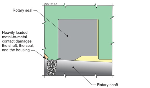
Although a small extrusion gap reduces seal extrusion damage, the unpredictable nature of shaft runout, misalignment, and deflection make it extremely difficult to predict how small an extrusion gap can be without risking destructive, heavily-loaded contact between the housing and the rotating shaft. If such contact occurs, the seal running surface may be destroyed, the seal housing may be damaged in ways that accelerate extrusion damage (Figure 6), and enough frictional heat may be generated to dramatically reduce the extrusion resistance of the seal material. In other words, rapid seal failure can occur if inadvertent heavily-loaded metal-to-metal contact occurs at the extrusion gap. This is the biggest challenge the mechanical designer faces when implementing a high-pressure rotary seal: how to implement the smallest-possible extrusion gap while avoiding heavily-loaded metal-to-metal contact.
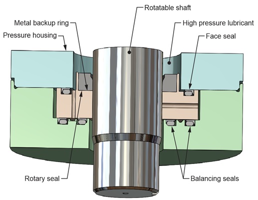
The floating backup ring (Figure 7) overcomes the challenges of shaft runout, misalignment, and deflection by aligning on the shaft and moving laterally with lateral shaft motion. This allows the smallest practicable extrusion gap clearance to be used, without risk of heavily loaded metal-to-metal contact. The features that allow the floating backup ring to follow lateral shaft motion are explained in the video. One key feature is hydraulic force balance in the axial direction that is established by strategically placed low friction “balancing seals”. Engineers who are seeking the most reliable high-pressure rotary seal performance should seriously consider the advantages provided by the floating backup ring.
Understanding the negative impacts of pressure-related hardware deformation
High pressure causes radial deformation of the components that contain it; e.g., the housing and shaft. The magnitude of pressure-related housing and shaft deformation increases with diameter.
Pressure within the housing causes the housing to expand radially outward, which increases the extrusion gap and bearing mounting clearances. The increase in extrusion gap clearance accelerates extrusion damage to the rotary seal, because the larger gap is more difficult to bridge. The increase in bearing mounting clearance accelerates extrusion damage by increasing dynamic runout.
High pressure also affects extrusion gap clearance by causing radial deformation of a hollow shaft. Such deformation includes a sloping region caused by the high-pressure boundary established by the rotary seal. When a hollow shaft conducts a high-pressure fluid, shaft deformation can be complex, including inward deformation at some locations, and outward deformation at others.
The floating backup ring is separate from the pressure housing, which provides immunity to pressure-induced expansion of the extrusion gap. As explained in the video, the design of the floating backup ring takes advantage of hydraulic force to substantially match the pressure-related deformation of the backup ring to the pressure-induced deformation of the shaft. These features allow the use of a small and dimensionally stable extrusion gap clearance, for optimal high-pressure extrusion resistance.
Understanding the negative impact of seal-generated heat
Polymeric rotary shaft seals generate significant heat during operation, and this heat increases with pressure and speed. Increasing seal temperature causes a significant reduction in the modulus of polymeric seal materials, which reduces their extrusion resistance. The heat is generated at the interface where sliding occurs between the seal and shaft, increasing the temperature of both. This causes differential thermal expansion between the shaft and housing, which must be taken into consideration when determining an appropriate extrusion gap clearance for larger diameter equipment.
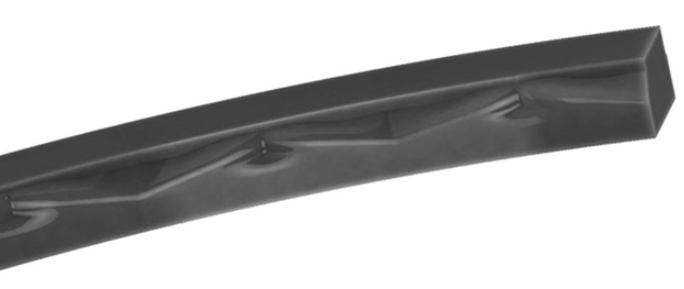
Kalsi-brand rotary shaft seals have patented features (Figure 8) that cause them to hydroplane on a lubricant film during shaft rotation, instead of sliding directly on the shaft. This low friction feature allows them to run cooler than non-hydrodynamic seals, reducing asperity contact-related seal wear and temperature-related modulus loss, and reducing thermal expansion of the shaft. Even with this hydrodynamic interfacial lubrication, however, rotation produces detrimental levels of seal-generated heat due to shearing of the interfacial lubricant film.
In all but the slowest speed equipment, active cooling improves high pressure rotary seal performance by reducing temperature-related loss of modulus and other material properties. Since the seal-generated heat is deposited into the shaft, the most effective heat dissipation method is circulation of a fluid that is in contact with the shaft near the rotary seal. In some types of equipment, active cooling is provided by the normal flow of process fluid around or through the shaft. In other types of equipment, the fluid inboard or outboard of the shaft must be circulated solely for the purpose of heat transfer. For additional information on heat transfer considerations with dynamic seals, see Chapter D8 of our rotary seal handbook.
Contact our staff for additional high pressure seal information

We have been involved in high pressure seal research and development since 1968, and are the world-wide leaders in the field. The combination of our floating backup rings and high-performance rotary seals is a state-of-the art achievement that will be difficult to surpass, although we work at it continuously. The industry leaders who developed this innovative floating seal technology are available to personally assist you with implementation. Contact Kalsi Engineering to request a quote, or for additional information.