Kalsi Engineering has tested various prototype rotary shaft seal designs where the pressure of the drilling fluid is 100 psi (6.89 bar) greater than the pressure of the seal lubricant. Through this effort we learned that this “reverse” pressure condition tends to encourage the seal to slip circumferentially in the seal groove. We also observed that abrasive wear of the seals was appreciably worse when such slippage occurs.
We experimented with various features directed at reducing slippage, including anti-rotation tangs molded on the seal. Through this effort we were able to develop a tang configuration and location that didn’t negatively impact other critical aspects of seal performance. We were also able to develop an economical way to incorporate mating anti-rotation features in the seal gland.
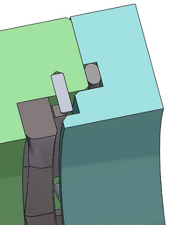
We obtained the best reverse pressure seal performance by placing axially projecting anti-rotation tangs near the outer edge of the environmental end of the rotary seal, as shown in Figure 1 (patent pending). These tangs engage inexpensive grooved pins that are mounted in radially oriented drilled holes in the groove bore. This type of pin has longitudinal ridges that produce an interference fit with the drilled hole, eliminating the need for high-precision reamed holes. A circular shelf projecting from the environment side gland wall prevents inadvertent pin loss and supports the rotary seal when the shaft is installed from left to right.
We performed two rotary tests of the sealing arrangement shown in Figure 1. The O-ring was needed to contain the drilling fluid in our test fixture but may not be needed in many applications. The rotary seal, PN 701-10-11, was tested on a 3.000” (76.2mm) shaft turning at 400 rpm (314 sfpm). An ISO 680 viscosity grade synthetic hydrocarbon seal lubricant was used in both tests. The bulk lubricant temperature was maintained at 162°F (72.2°C) and the drilling fluid was replaced daily. As with all Kalsi-brand rotary shaft seal designs, the dynamic lip of the PN 701-10-11 seal incorporates patented hydrodynamic waves that pump a film of the lubricant into the dynamic sealing interface during shaft rotation to reduce friction and wear.
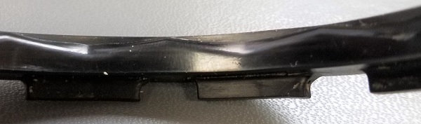
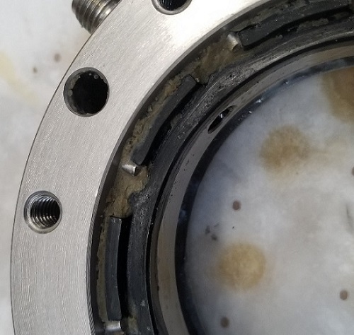
We stopped the first test (reverse pressure test no. 67) at 125.78 hours to observe seal condition. The condition of the dynamic surface of the used seal was excellent, as shown in Figure 2. At the end of the test, the tangs were resting on the pins (Figure 3) which indicates that the seal would have slipped circumferentially within the gland if not for the tang and pin arrangement.
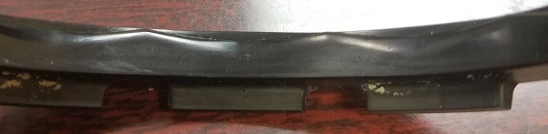
We stopped the second test (reverse pressure test no. 68) at 138.57 hours to observe seal condition. The condition of the dynamic surface was excellent at the conclusion of the test, as shown in Figure 4. As with the previous test, the tangs were resting against the pins at the conclusion of the test, indicating that the tang and pin arrangement prevented slippage.
Although laboratory testing is no substitute for customer field evaluation in actual operating conditions, it does allow the performance of alternative seal designs to be compared. Based on the excellent condition of the used PN 701-10-11 test seals, compared to other seals we have tested, we believe this new seal design is ready for field evaluation in oilfield applications where the pressure of the drilling fluid is up to 100 psi greater than the pressure of the seal lubricant. We will continue to perform laboratory testing, including tests at higher levels of “reverse” pressure, and tests with intentional shaft runout. Contact us for additional information about this exciting new rotary shaft seal design.