Kalsi Engineering, Inc. (KEI) pioneered the development of advanced gate valve methodology that is used to account for the flow-induced forces and complex interactions between the stem and gate, gate and guide rail, and gate and seats for opening and closings strokes. The methodology is especially designed for valves that are subject to high flow conditions including High Energy Line Break (HELB). KEI initiated development of advanced gate valve methodology as part of an SBIR funded project for the NRC which is documented in NUREG/CR-5807 [6]. KEI’s early work later became the foundation for the gate valve model for the EPRI PPM program.
Recently, the High Flow Model was completely re-coded by KEI and added as an optional module to the Kalsi Valve and Actuator Program (KVAP®) that is only available only to clients who are EPRI NMAC members. KEI’s successful role in the development and validation of the advanced gate valve model was a crowning achievement that helped solidify KEI’s position in the nuclear power industry as an engineering firm that deftly applied first principles and technical rigor to provide fundamentally sound solutions to challenging problems.
Although the High Flow Model made its first appearance in KVAP 4.1 (released 2016), the nascency of the model development was tied to events related to the Unit 2 Three Mile Island (TMI) accident, which occurred on March 28, 1979.
As part of the NRC (US Nuclear Regulatory Commission) and Industry response to the TMI accident, an EPRI test program was initiated that focused on key elements of the emergency cooling system and the safety valves. One objective of the test program was to evaluate some of the common valves that were used as block valves for pilot-operated relief valves (PORVs). PORV block valves are motor-operated gate valves that serve to block flow from the pressurizer to the PORV. The test program revealed that three of the seven block valves that were selected for testing failed to fully close after repeated use under test conditions. This finding resulted in the NRC issuing NRC bulletin No 81-02 [1].
In the following years, the nuclear industry experienced several gate valve issues. In 1985 at the Davis-Besse nuclear power plant, a normally open motor-operated gate valve failed to reopen resulting in a complete loss of Main and Auxiliary Feedwater. The failure to reopen was attributed to higher-than-expected stem torque/thrust which caused the torque switch in the open direction to trip and prevented the gate from properly opening [2].
Valve performance issues noted in NRC Bulletin 81-02 [1], NRC Bulletin 85-03 [2], and NRC Generic Safety Issue 87 [3] led to an NRC sponsored test program lead by Idaho National Engineering Laboratory (INEL) [4] and [5].
The operating conditions for the INEL test program included blow down conditions consistent with those present during a HELB accident scenario. The energy levels associated with HELB or blow down conditions can be seen in this video taken during testing at Wyle Laboratories (now NTS Huntsville).
Test results from [4] and [5] and prior industry experience with valve required thrust exceeding calculated thrust values led to the issuance of NRC Generic Letter 89-10 [5]. The scope of testing at INEL was expanded and the test program update was provided in [7].
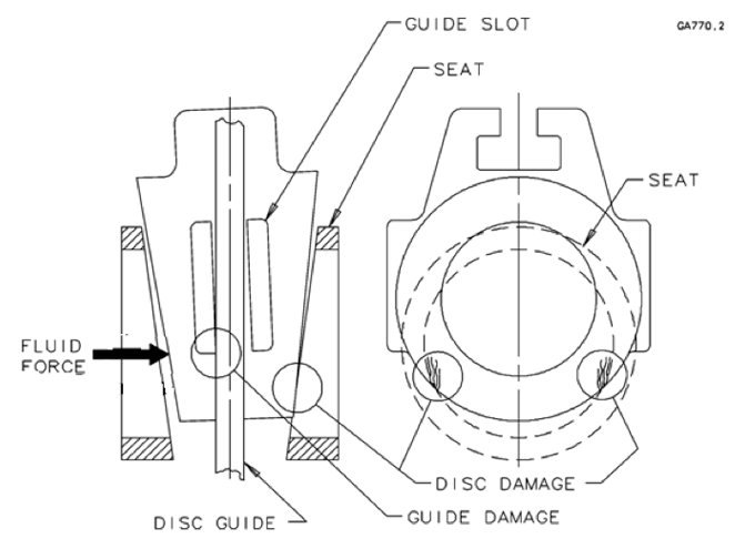
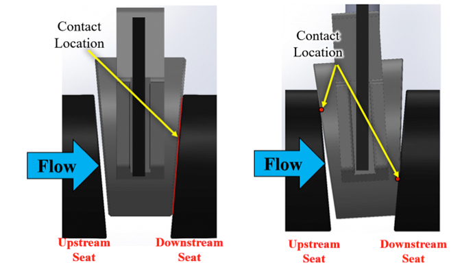
One of the main objectives of this test program in [4] was to “determine what factors affect the performance of motor-operated gate valves and to determine how well Industry’s analytic tools predict that performance.” During gate valve testing under high flow conditions, gate (often referred to in industry documents as disk or disc), seat, guide slot and guide rail damage occurred (see Figure 1 for an example of gate and guide slot damage) due to unexpected gate tipping while in contact with the downstream seat (see Figure 2). Key conclusions of the NRC test program [5] were as follows:
- Special industry sizing equation using the standard variables did not conservatively estimate the total thrust needed to close the tested valves.
- Disc factors [(i.e., valve factor)] higher than the normal disc factor value of 0.3 were encountered.
- The valve thrust equation … needs to better model the behavior of valves exposed to slightly subcooled fluid.
- The thrust sizing equation [used by manufacturers] is not applicable to valves that sustain damage (such as galling and plastic deformation of the sliding surfaces) at design basis loadings.
The level of damage and corresponding increase in required thrust to operate the valve brought into question the survivability of key components of critical motor-operated gate valves during accident scenarios and cast doubt on the reliability of the required thrust prediction for these valves especially for high flow applications. The industry recognized the need to develop a more advanced gate valve methodology and to develop an extensive collection of test data to validate the model.
![Figure 1 Damage on a) downstream seating faces and gate slot due high flow-induced forces during testing. Damage to the slot b) occurred while the gate was tipped on the rail. Damage to the gate seat face initially occurred due to edge-on-edge scissoring action between the gate and seat inner diameter. Additional damage to the gate seat face occurred after it transitioned to flat-on-flat contact [5].](https://www.kalsi.com/wp-content/uploads/2021/03/damage.jpg)
The KEI Valve Design Effects Test Fixture
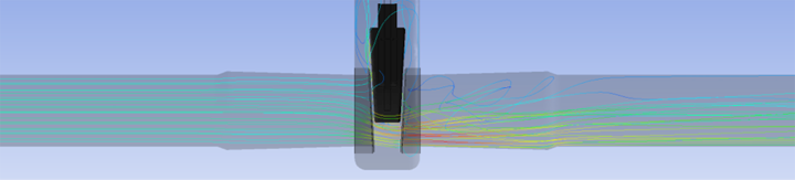
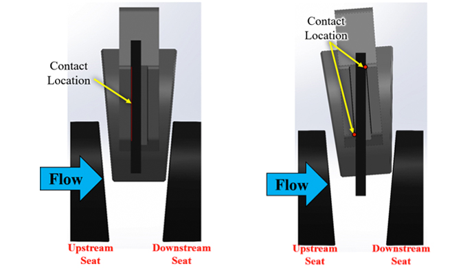
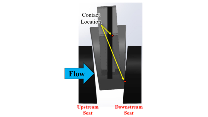
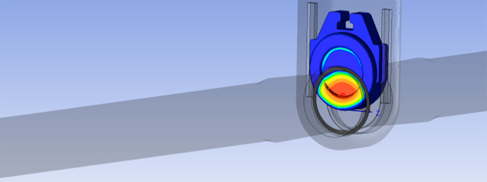
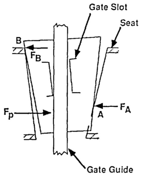
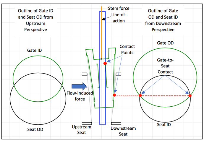
The gate valve model includes a Gate Equilibrium Model that is used to identify the contact mode by determining the stem forces acting on the gate such that all applied forces and moments balance. Two key contributors to the force and moment balances are the flow-induced forces and moments and the contact and sliding friction forces associated with the gate-to-seat and/or gate to rail reaction points. The magnitude and the line-of-action of the flow-induced force acting along the pipe axis are due to the pressure impinging on the gate. The region of high differential pressure on the gate generally aligns with the portion of the gate visible through the seat bore when down the pipe axis (see Figure 6). An example of the equilibrium model (which uses the flow-induced force and moment from the pressure field in Figure 6) and underlying free-body diagram is shown in Figure 7.
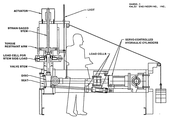
In order to ensure the resulting methodology was sound, test data was required to validate the complex kinematics and friction algorithms and show they were properly developed and integrated into a calculation routine. Testing gate valves under HELB conditions posed a significant financial burden to the nuclear power industry. To curtail the cost of performing a large matrix of gate valve tests, the nuclear industry approached KEI seeking alternative test methods. Since a significant cost component was due to operating the large energy source required to produce high flow rates, KEI recognized that significant cost savings could be achieved if a fixture could be used to apply the required forces to the gate that would accurately simulate the tipped-mode flow-induced forces and moment present during flow testing (see Figures 3 to 7). To achieve this goal, KEI designed the Valve Design and Effects Test Fixture shown as Figure 8. The fixture uses two servo-controlled hydraulic cylinders to apply a pair of position-dependent forces to the gate that produce the same total force (in the pipe axis direction) and moment as a flowing fluid under the desired pressure and flow rate conditions. The fixture was designed so that a parametric study including different gate and seat sizes, rail-to-slot clearances, materials pairs, and operating temperatures could be performed. The fixture was used to develop an extensive library of data that was used to validate the gate valve model.
KVAP Gate Valve Key Features
For EPRI NMAC members, the High Flow Model is available in KVAP for standard and Westinghouse gate-designs.
KEI developed other enhanced tools to help visualize the gate contact modes through the progression of valve operation.
KEI performed an ANSYS simulation that shows the transition from fully tipped on the rail through fully tipped on the seat and finally flat on the seat. The ANSYS animation can be viewed here:
KEI developed a Motion Study simulation in SolidWorks that shows the corresponding thrust values based on the flow-induced forces and moments and the interactions between the gate and the rail and seats. The Motion Study animation can be viewed here:
Although these tools provide excellent insights into loads and stresses, they are difficult to set up and take considerably time to solve. KEI developed the Contact Mode Viewer using the kinematic model that is part of the High Flow Model and integrated into KVAP. The Contact Mode Viewer can be used to see the contact mode, forces, and other outputs at any gate position. The Contact Mode Viewer is based on the KVAP and calculation results including differential pressure forces based on the system conditions modeled. An example of the gate contact mode viewer is provided as Figure 9. The Contact Mode Viewer is currently available only to KEI personnel.
Contact the Kalsi Engineering Consulting staff to learn more about KVAP and our extensive gate valve testing and analysis experience.
References
[1] NRC Bulletin 81-02: Failure of Gate Type Valves to Close Against Differential Pressure, 1981.
[2] NRC Bulletin 85-03: Motor-Operated Valve Common Mode Failures During Plant Transients Due to Improper Switch Settings, 1985.
[3] NUREG-0933 Resolution of Generic Safety Issue 87: Failure of HPCI Steam Line Without Isolation, Rev. 2, 2011.
[4] NUREG/CR-5406, “BWR Reactor Water Cleanup System Flexible Wedge Gate Isolation Valve Qualification and High Energy Flow Interruption Test, Idaho National Laboratories, 1989.
[5] NUREG/CR-5558, “Generic Issue 87: Flexible Wedge Gate Valve Test Program, Phase II Results and Analysis”, US NRC, 1991.NRC Generic Letter 89-10, “Safety-related Motor-Operated Valve Testing and Surveillance Results of the Public Workshops”, NRC, 1989.
[6] NUREG/CR-5807, “Improvements in Motor Operated Gate Valve Design and Prediction Models for Nuclear Power Plant Systems,” May 1992.
[7] NUREG/CR-5720, “Motor-Operated Valve Research Update, US NRC, 1992.
[8] Valve Design Effects Testing Results, Kalsi Engineering Document No. 1795 Draft 2, May 12, 1993.